How to Reduce Heat Damage in Metallographic Cutting?
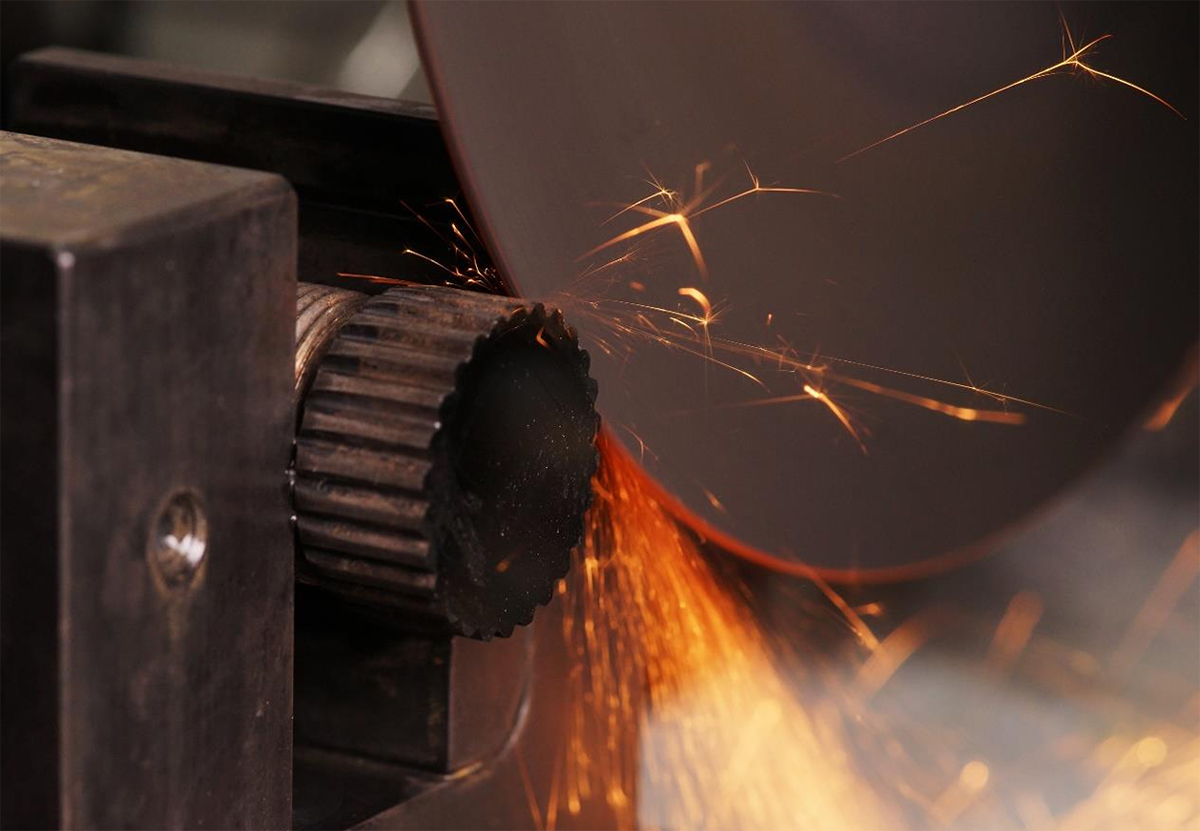
Sectioning is the first critical step in metallographic specimen preparation. The purpose of sectioning is not merely to reduce a material to an observable size, but to obtain a representative cross-section without altering its original microstructure. When excessive heat is generated during sectioning, the specimen surface may undergo tempering, rehardening, phase transformation, oxidation discoloration, plastic deformation, microcracking, or the development of residual stresses. These thermal effects and mechanical damage may persist through subsequent grinding and polishing processes, ultimately leading to misinterpretation of the material's original microstructure during microscopic examination.
This article identifies five primary sources of thermal damage during metallographic sectioning: improper cutting wheel selection, excessive feed rate, insufficient cooling, unstable specimen clamping, and inappropriate cutting paths. The findings indicate that minimizing thermal damage cannot be achieved simply by reducing the cutting speed. Instead, it requires simultaneous control of cutting wheel hardness and abrasive type, coolant flow rate and direction, feed load, specimen fixturing rigidity, and post-sectioning surface inspection. By establishing standardized sectioning parameters, laboratories can significantly reduce specimen rework, edge distortion, and the risk of incorrect microstructural interpretation.
1. Introduction: Reliable Metallographic Results Begin with Proper Sectioning
ASTM E3 states that the purpose of metallographic examination is to reveal the composition and microstructure of metals and alloys, and that specimen selection and preparation have a significant influence on the quality of the results. In other words, reliable metallographic images are not created only under the microscope; they are the result of every preparation step, including sampling, sectioning, mounting, grinding, polishing, and etching.
Among all specimen preparation procedures, sectioning is one of the most frequently overlooked. One reason is that thermal damage caused during cutting is not always immediately visible. Some materials exhibit obvious burn discoloration, whereas others reveal abnormal surface microstructures only after microscopic examination. If such damage is not identified immediately after sectioning, considerable time may be spent on grinding and polishing without ever obtaining a reliable metallographic image.
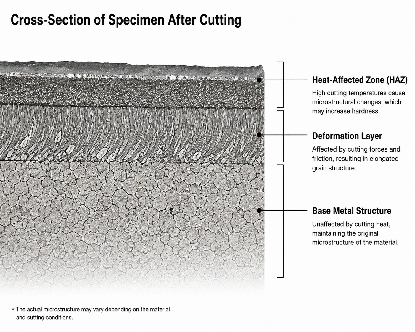
Figure 1. Mechanism of Heat-Affected Zone Formation During Metallographic Sectioning

2. Research Question: What Is Thermal Damage During Metallographic Sectioning?
Thermal damage during sectioning refers to the alteration of the specimen surface caused by localized temperature rise, friction, compression, or tensile forces during the cutting process. It may result solely from thermal effects or from the combined effects of heat and mechanical deformation. In metallographic analysis, the primary concern is not whether the cut surface appears visually acceptable, but whether the cross-section still accurately represents the material's original microstructure.
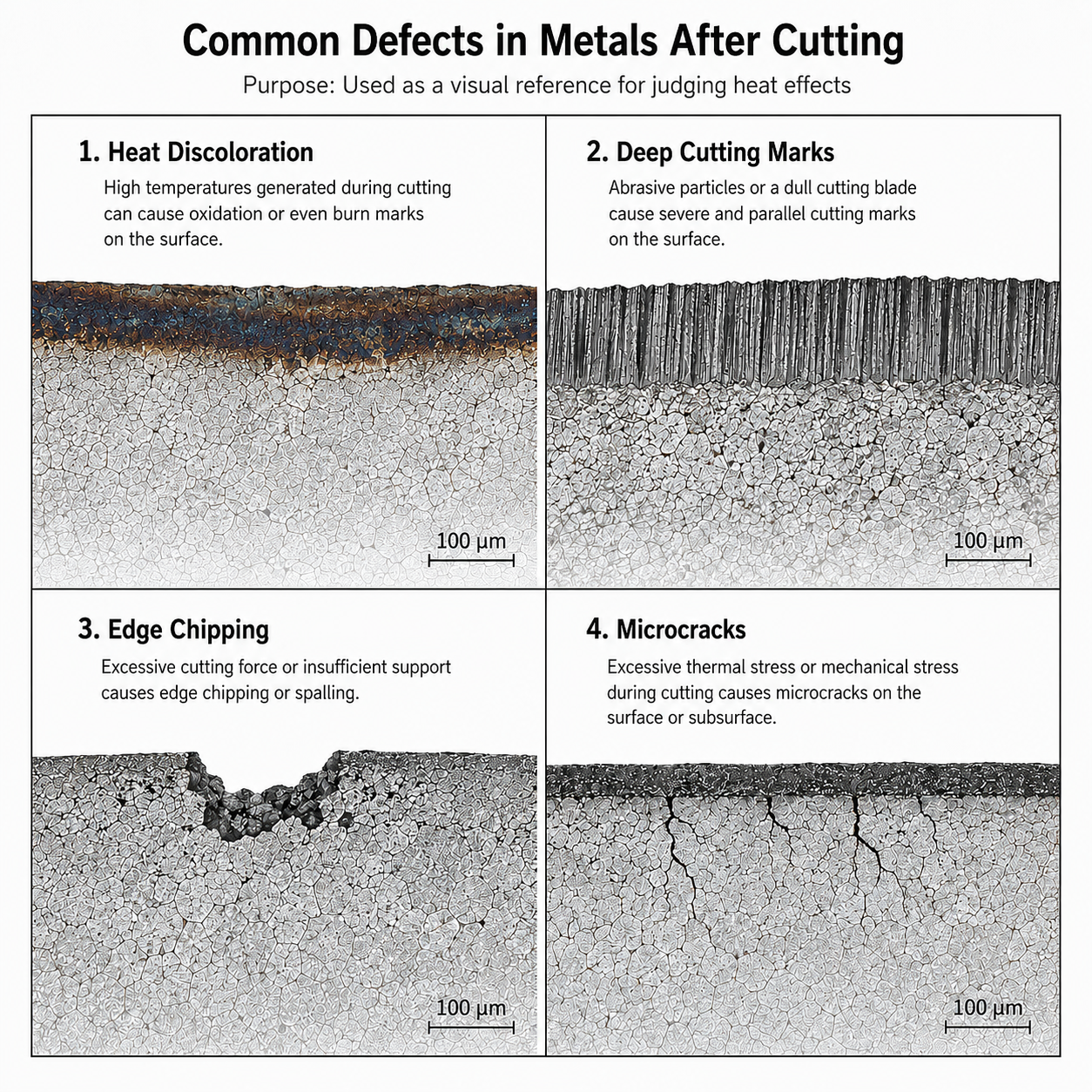
Common forms of thermal damage include:
| Type of Thermal Damage | Surface or Microscopic Characteristics | Impact on Metallographic Interpretation |
|---|---|---|
| Oxidation Discoloration | Blue, yellow, or black discoloration on the cut surface | Indicates excessive localized heating and possible microstructural alteration |
| Tempering or Softening | Reduced surface hardness | Distorts hardness measurements and heat-treated microstructures |
| Rehardening or Phase Transformation | Abnormal white layer or hardened surface layer | May be mistaken for an original hardened layer |
| Plastic Deformation Layer | Elongated grains and blurred grain boundaries | Interferes with grain size, phase boundary, and crack evaluation |
| Microcracks | Fine cracks at the edge or within brittle phases | May lead to incorrect conclusions in failure analysis |
| Edge Chipping | Notches or material loss along the cut edge | Reduces the accuracy of coating and surface layer measurements |
3. Major Sources of Thermal Damage During Sectioning
3.1 Improper Cutting Wheel Selection
A cutting wheel is not necessarily better simply because it is harder or thinner. The abrasive type, bond hardness, thickness, and self-sharpening characteristics of the cutting wheel all influence the amount of heat generated during sectioning.
If the cutting wheel is too hard, abrasive grains are less likely to detach and renew, causing the cutting surface to become dull and increasing frictional heat. If the cutting wheel is too soft, excessive wear occurs, reducing cutting stability.
The harder, tougher, or more prone to work hardening a material is, the more important it becomes to select a cutting wheel that maintains cutting efficiency while minimizing excessive friction.
Common evaluation methods:
- A significant increase in sparks during sectioning may indicate excessive friction.
- A sharper cutting sound may indicate a dull cutting wheel or excessive cutting load.
- A bright cutting surface that is difficult to grind afterward may indicate surface work hardening.
- Abnormally rapid cutting wheel wear may indicate that the wheel is too soft or incompatible with the material.
3.2 Excessive Feed Rate
When the feed rate is too high, the cutting wheel must remove more material within a given time, increasing the load in the cutting zone. As a result, heat generation and mechanical deformation also increase. In many laboratories and production environments, operators increase the feed rate to shorten sampling time; however, this often transfers the time cost to subsequent regrinding, repolishing, or recutting processes.
An appropriate feed strategy should allow the cutting wheel to maintain stable cutting performance rather than forcing excessive pressure onto the material. For high-hardness steels, heat-treated components, ceramics, cemented carbides, thermal spray coatings, and coated specimens, lower cutting loads combined with stable cooling should be applied. When necessary, pulsed or stepwise feeding can be used to allow sufficient cooling and chip removal in the cutting zone.
3.3 Insufficient or Improperly Directed Coolant
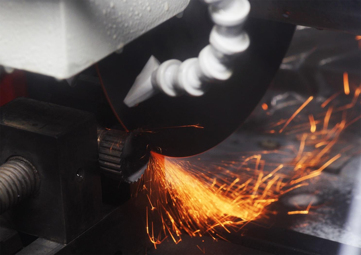
Coolant performs three essential functions: removing heat, flushing away chips, and reducing cutting wheel loading. If coolant is sprayed only onto the outer surface of the cutting wheel without reaching the actual cutting contact zone, the surface may appear wet while heat remains concentrated inside the specimen. Insufficient coolant concentration or contaminated coolant can also reduce cooling and lubrication effectiveness.
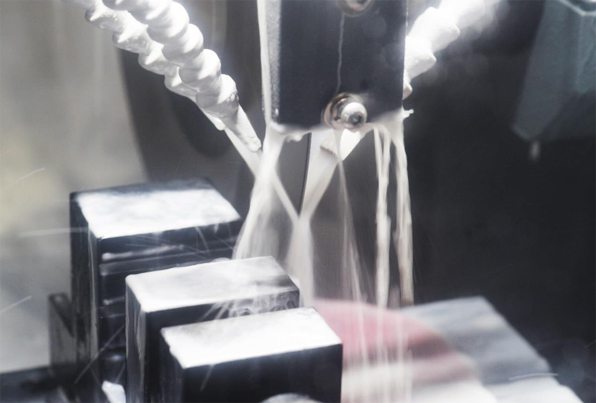
Figure 2: Comparison Between Effective and Ineffective Cooling
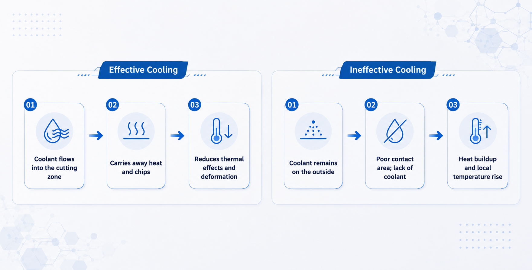
Coolant must reach the cutting contact zone to be effective. Simply wetting the surface of the cutting wheel does not guarantee sufficient cooling.
3.4 Vibration and Localized Friction Caused by Unstable Clamping
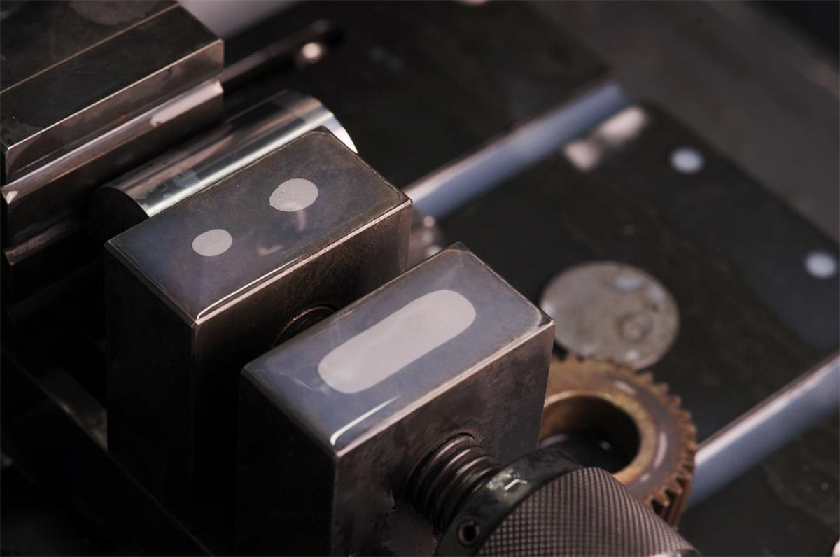
Unstable specimen clamping can cause vibration, movement, and increased localized contact pressure. These issues not only increase cutting marks but also cause heat to concentrate in specific areas. Small specimens, irregularly shaped parts, tubes, thin sheets, and coated samples are particularly susceptible to damage caused by inadequate fixation.
The principle of specimen clamping is to ensure that the sample does not slip, warp, or experience excessive single-point pressure during sectioning. When necessary, auxiliary supports, resin mounting, soft pads, or dedicated fixtures may be used; however, supporting materials must not interfere with cutting safety.
3.5 Improper Cutting Path and Sampling Direction
The cutting path affects heat distribution and subsequent metallographic interpretation. If the cutting process directly enters the most critical analysis surface, thermal damage may be concentrated in the exact area requiring examination. For coatings, welds, cracks, failure origins, and surface-treated layers, the analysis objective should be defined first, followed by determination of the cutting direction and required material allowance.
Sufficient grinding allowance should be retained so that subsequent grinding can remove sectioning damage; however, excessive reliance on grinding for correction should be avoided. If the heat-affected layer is too deep, grinding time will increase and edge geometry may also be compromised.
4. How to Determine Whether Sectioning Has Caused Thermal Damage?
After sectioning, a quick inspection should be performed before proceeding to mounting and grinding. Early identification of potential issues can prevent defective cut surfaces from being carried into subsequent preparation processes.
| Inspection Item | Observation Method | Abnormal Indications |
|---|---|---|
| Visual Color | Inspect the cut surface and edges | Blue, yellow, or black discoloration; localized burn marks |
| Edge Condition | Use a magnifying glass or low-magnification microscope | Edge chipping, burrs, cracks, coating delamination |
| Cutting Marks | Observe directional marks under low magnification | Deep grooves or uneven wave-like patterns |
| Hardness Comparison | Compare surface and internal microhardness values | Abnormally increased or decreased surface hardness |
| Etching Response | Observe after mild etching | Different etching response between surface layer and interior |
| Subsequent Grinding | Evaluate material removal during grinding | Sectioning damage remains after extended grinding |
5. Five Control Strategies to Minimize Thermal Damage During Sectioning
5.1 Define the Analysis Objective Before Selecting Sectioning Conditions
Different analysis objectives have different tolerance levels for thermal damage. For general microstructural observation, sectioning damage may be removed through sufficient grinding allowance. However, when examining surface hardened layers, decarburized layers, coating thickness, crack origins, or weld heat-affected zones, more conservative sectioning conditions must be applied.
Recommended practices:
- Mark the observation surface and sampling direction before sectioning.
- Maintain sufficient grinding allowance for critical observation surfaces.
- Avoid cutting directly through the failure origin.
- Perform low-load trial sectioning for heat-sensitive materials.
5.2 Select a Cutting Wheel Suitable for the Material
Material hardness, toughness, and thermal conductivity all influence cutting wheel selection. High-hardness materials require a cutting wheel that maintains cutting efficiency, while soft and ductile materials require conditions that prevent wheel loading and dragging. When the cutting wheel is not suitable for the material, operators often compensate by applying higher pressure, which can increase thermal damage.
| Material Type | Sectioning Risks | Key Control Measures |
|---|---|---|
| Heat-Treated Steel | Tempering, rehardening, white layer formation | Low load, sufficient cooling, appropriate abrasive selection |
| Stainless Steel | Work hardening, dragging | Avoid excessive pressure and maintain cutting wheel sharpness |
| Aluminum Alloy | Adhesion, wheel loading, burr formation | Use non-loading cutting conditions with adequate cooling |
| Cast Iron | Graphite pull-out, edge cracking | Ensure stable clamping and minimize vibration |
| Coated Components | Edge delamination, inaccurate thickness measurement | Provide proper support and avoid aggressive cutting from the coating side |
| Ceramics or Brittle Materials | Chipping, microcracks | Control feed rate, provide stable support, reduce impact loading |
5.3 Control Feed Rate and Sectioning Load
The feed rate should be determined based on the actual cutting condition rather than only the material thickness. During stable sectioning, the cutting sound, spark generation, coolant discharge condition, and cutting wheel load should remain consistent. If the cutting sound becomes sharper, sparks suddenly increase, coolant evaporation becomes obvious, or the motor load rises, it indicates that excessive heat may be accumulating in the cutting zone.
In practical applications, the principle of "slow feed rate, stable load, and continuous cooling" should be followed. For large or thick specimens, step-by-step sectioning can be applied to avoid prolonged high-load cutting conditions.
5.4 Ensure Coolant Properly Reaches the Cutting Contact Zone
Coolant flow rate, direction, concentration, and cleanliness must all be properly controlled. If the nozzle is misaligned, coolant may only reach the outer area of the cutting wheel. If chips accumulate in the cutting gap, coolant cannot effectively enter the cutting zone.
On-site inspection checklist:
- Is the nozzle correctly aimed at the contact area between the cutting wheel and specimen?
- Does the coolant effectively remove chips from the cutting gap?
- Does the coolant concentration comply with equipment and consumable recommendations?
- Is the circulating coolant contaminated or containing excessive metal particles?
- Is smoke, vapor, or a burning odor generated during sectioning?
5.5 Perform Low-Magnification Inspection Immediately After Sectioning
Low-magnification inspection after sectioning is one of the most effective practices for reducing rework. If burn marks, cracks, or deep grooves are detected, the sectioning parameters should be adjusted before proceeding to grinding. Excessive thermal damage not only increases grinding time but may also remove the surface layer that is critical for observation.
6. Sectioning Parameter Record Sheet
Establishing a sectioning parameter record makes it easier to trace the causes of rework. The following information should be recorded at minimum:
| Item | Details |
|---|---|
| Material | Material type, heat treatment condition, hardness, dimensions |
| Analysis Objective | Grain size, coating, weld bead, cracks, hardened layer, failure analysis |
| Cutting Wheel | Model, thickness, abrasive type, service condition |
| Feed Conditions | Feed rate, cutting load, whether stepwise sectioning was applied |
| Cooling Conditions | Coolant type, concentration, nozzle position, flow condition |
| Clamping Method | Fixture type, support position, auxiliary fixation for irregular specimens |
| Post-Sectioning Inspection | Presence of discoloration, edge chipping, cracks, or deep scratches |
| Final Result | Whether regrinding, repolishing, or recutting was required |
7. Conclusion: Preventing Thermal Damage Requires Management of Heat, Load, and Support Conditions
Thermal damage during sectioning is not caused by a single factor; it results from the combined effects of cutting wheel selection, feed rate, cooling conditions, specimen clamping, and sampling direction. Simply reducing cutting speed is not sufficient if cutting wheel compatibility, coolant direction, or fixture rigidity are not properly improved.
For metallographic laboratories, the most effective approach is to treat sectioning as a controllable process: define the analysis objective before sectioning, maintain stable cutting load and cooling during sectioning, and immediately inspect the surface and edges afterward. When sectioning damage is controlled within a removable range, subsequent mounting, grinding, polishing, and etching processes can successfully reveal the true microstructure of the material.
References
- ASTM International, ASTM E3 - Standard Guide for Preparation of Metallographic Specimens
- ASTM International, ASTM E407 - Standard Practice for Microetching Metals and Alloys
- ASM Handbook, Volume 9: Metallography and Microstructures
- Vander Voort, G. F., Metallography: Principles and Practice
Editor
Cheng-Ping Kuo, Manufacturing Department, Taiwan Nakazawa Co., Ltd.
Related Press Release
-
 2026 08-19Exhibition
Automation Taipei 2026
Date: 19 – 22 AUG. 2026
Venue: Taipei Nangang Exhibition Center, Hall 1
Booth NO.: J204 -
 2026 07-17Knowledge
Understanding Metallographic Specimen Rework and Its Causes
The purpose of metallographic analysis is to reveal the internal microstructure of a material in a reliable and reproducible manner for observation and interpretation. When the specimen surface contains scratches, smearing, deformation layers, edge rounding, contamination, under-etching, or over-etching, the microscopic image may no longer represent the material itself but instead reflect artifacts introduced during specimen preparation. Under such circumstances, specimen rework is often required.
-
 2026 05-13Knowledge
How to Choose the Right Grinding Wheel?
Cutting: The Key to Successful Metallographic Analysis...
-
 2025 10-21Exhibition
2025 TiTE x IHT
Date: October 21–23, 2025
Venue: Taichung International Convention and Exhibition Center (Shuinan) -
 2025 08-20Exhibition
Automation Taipei 2025
Date: 20 – 23 AUG. 2025
Venue: Taipei Nangang Exhibition Center, Hall 1
Booth NO.: J1026 -
 2025 06-11Knowledge
Inverted vs. Upright Metallurgical Microscopes: How Do They Differ from Regular Microscopes?
In the process of modern metal material analysis and quality inspection, metallurgical microscopes play an extremely critical role. The quality of metallographic sample preparation and microscopic observation directly affects the reliability of testing data, which in turn influences a company's judgment on product quality and process optimization.