Understanding Metallographic Specimen Rework and Its Causes
The purpose of metallographic analysis is to reveal the internal microstructure of a material in a reliable and reproducible manner for observation and interpretation. When the specimen surface contains scratches, smearing, deformation layers, edge rounding, contamination, under-etching, or over-etching, the microscopic image may no longer represent the material itself but instead reflect artifacts introduced during specimen preparation. Under such circumstances, specimen rework is often required.
This article examines metallographic specimen rework from the perspective of the specimen preparation process and categorizes the primary causes into six major groups: thermal damage during sampling and cutting, insufficient support during mounting, incomplete removal of damage from previous grinding stages, mismatched polishing parameters, contamination during cleaning and drying, and uncontrolled etching conditions. Finally, a practical decision guide and preventive inspection checklist are provided to help laboratories reduce rework rates and improve the consistency of microstructural interpretation.
1. Introduction: Rework Is Not Failure—It Is a Signal
In metallographic laboratories, "rework" is often regarded as lost time: specimens must be reground, repolished, re-etched, or, in severe cases, recut and resampled. From a quality management perspective, however, rework is actually a valuable signal. It indicates that the current preparation process is not yet capable of presenting the true microstructure clearly and consistently.
ASTM E3 states that the primary objective of metallographic examination is to reveal the composition and structure of metals and alloys through optical or electron microscopy, and that specimen selection and preparation are critical to obtaining reliable results. In other words, the quality of a metallographic image does not begin at the microscope—it begins with the very first cut.
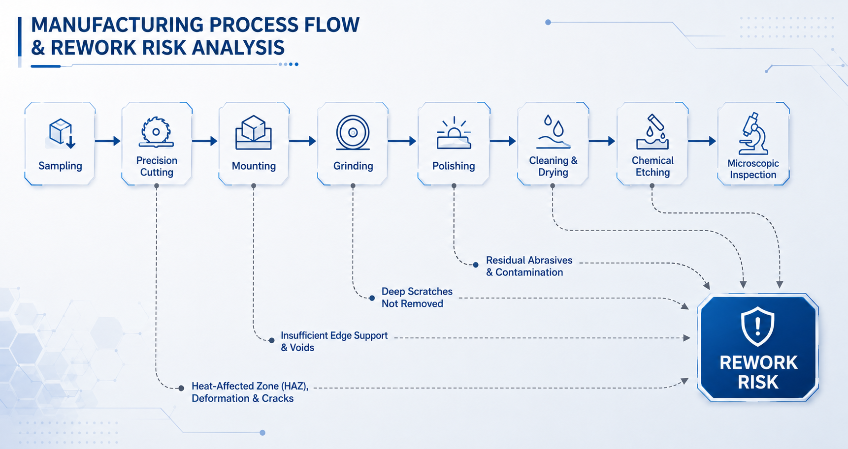
Figure 1. Stages Where Metallographic Specimen Rework Occurs
2. When Does a Metallographic Specimen Require Rework?
Whether a metallographic specimen requires rework depends on one fundamental question: Is the current image sufficient to support accurate interpretation?
If a defect only affects appearance without influencing interpretation, it may be acceptable. However, if it obscures grain boundaries, causes incorrect phase fraction evaluation, conceals cracks, or affects the positioning of hardness indentations, rework becomes necessary. Common evaluation criteria are summarized below:
| Observed Condition | Potential Impact | Rework Recommended? |
|---|---|---|
| Deep unidirectional scratches | Obscures grain boundaries, inclusions, or cracks | Yes |
| Surface smearing | Soft phases are smeared over, making secondary phases indistinct | Yes |
| Edge rounding | Distorts measurements of coating thickness, decarburized layers, and surface-treated layers | Yes |
| Under-etching | Grain and phase boundaries are not clearly revealed | Depends on the analysis objective |
| Over-etching | False porosity, exaggerated grain boundaries, inaccurate phase fraction estimation | Usually |
| Localized water stains or contamination | Reduces the accuracy of image analysis thresholds | Depends on the affected area |
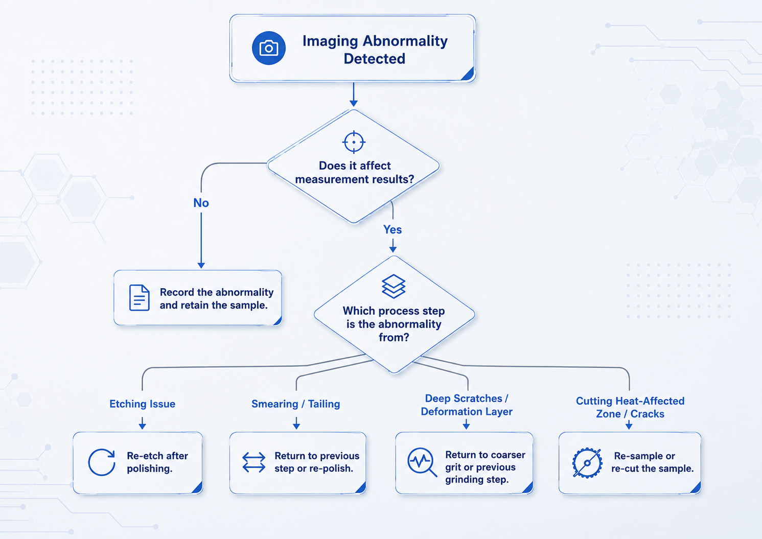
Figure 2. Rework Decision Tree
3. Six Major Causes of Metallographic Specimen Rework
3.1 Thermal Damage and Mechanical Deformation During Cutting
Cutting is one of the most underestimated sources of specimen rework. If the cutting wheel is improperly selected, the feed rate is too high, coolant is insufficient, or the specimen is inadequately clamped, the cut edge may suffer thermal damage, plastic deformation, microcracks, or microstructural changes. When the depth of this damage exceeds what can be removed during subsequent grinding, the polished specimen may still produce unreliable micrographs, even with a mirror-like finish.
Typical symptoms include:
- Discoloration or bluish burn marks along the cut edge.
- Noticeable differences between the surface microstructure and the underlying material.
- Microcracks or edge chipping in high-hardness materials.
- Persistent directional damage despite prolonged grinding.
Preventive measures include selecting the appropriate cutting wheel, ensuring sufficient coolant flow, maintaining stable clamping, and matching the cutting speed to the material's hardness. For heat-treated components, coated materials, welds, and failure analysis specimens, particular care should be taken to prevent the cutting process from altering the original microstructure.
Figure 3. Illustration of the Heat-Affected Zone Caused by Cutting
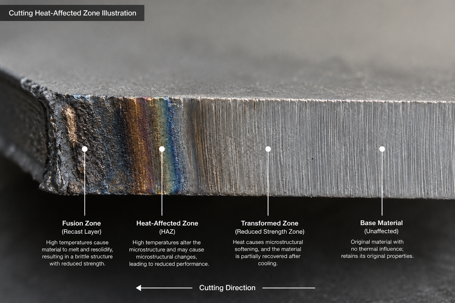
Image description: The right side shows a properly cut cross-section, while the left side illustrates a heat-affected zone caused by insufficient cooling. Labels indicate the "Original Microstructure," "Heat-Affected Layer," and "Material Removal Depth Required During Subsequent Grinding."
3.2 Insufficient Mounting Support Leading to Edge Rounding
The purpose of mounting is not merely to facilitate specimen handling but also to provide adequate edge support. When gaps, air bubbles, resin shrinkage, or significant hardness differences exist between the specimen and the mounting resin, grinding and polishing preferentially remove unsupported edges, causing edge rounding. For applications involving coating thickness measurement, case depth evaluation, decarburization analysis, oxide layer assessment, or failure crack analysis, edge rounding can directly lead to inaccurate measurements.
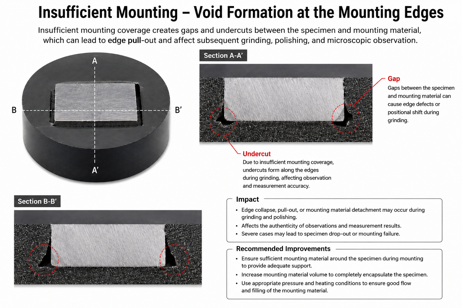
Typical symptoms include:
- The edge region cannot be brought into focus or exhibits abnormal brightness.
- The coating appears thinner than its actual thickness.
- Black lines or gaps are visible at the interface between the specimen and the mounting resin.
- The specimen edges become brighter than the center during polishing.
Recommended improvements include selecting low-shrinkage mounting materials, applying vacuum impregnation when necessary, optimizing hot-mounting pressure and temperature, and reducing excessive grinding or polishing pressure.
3.3 Incomplete Removal of Damage from the Previous Grinding Stage
The fundamental objective of grinding is to progressively remove the deformation layer and scratches introduced by the previous, coarser abrasive. If the grit size progression is too large, grinding time is insufficient, or grinding directions are not alternated and inspected, deep scratches may remain throughout the entire preparation process. Even prolonged final polishing often only rounds off the edges of these scratches rather than eliminating them completely.
A simple but effective rule is to verify that all scratches from the previous grinding direction have disappeared before proceeding to the next abrasive. If scratches from the previous step are still visible, the specimen should not advance to the next grinding stage.
Figure 4. Cross-Grinding Direction Verification Method
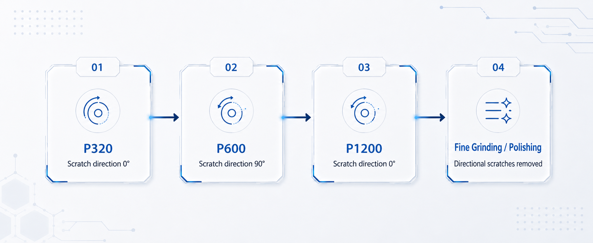
Alternating the grinding direction between successive steps allows operators to quickly verify whether damage from the previous grinding stage has been completely removed.
3.4 Mismatched Polishing Parameters and Material Characteristics
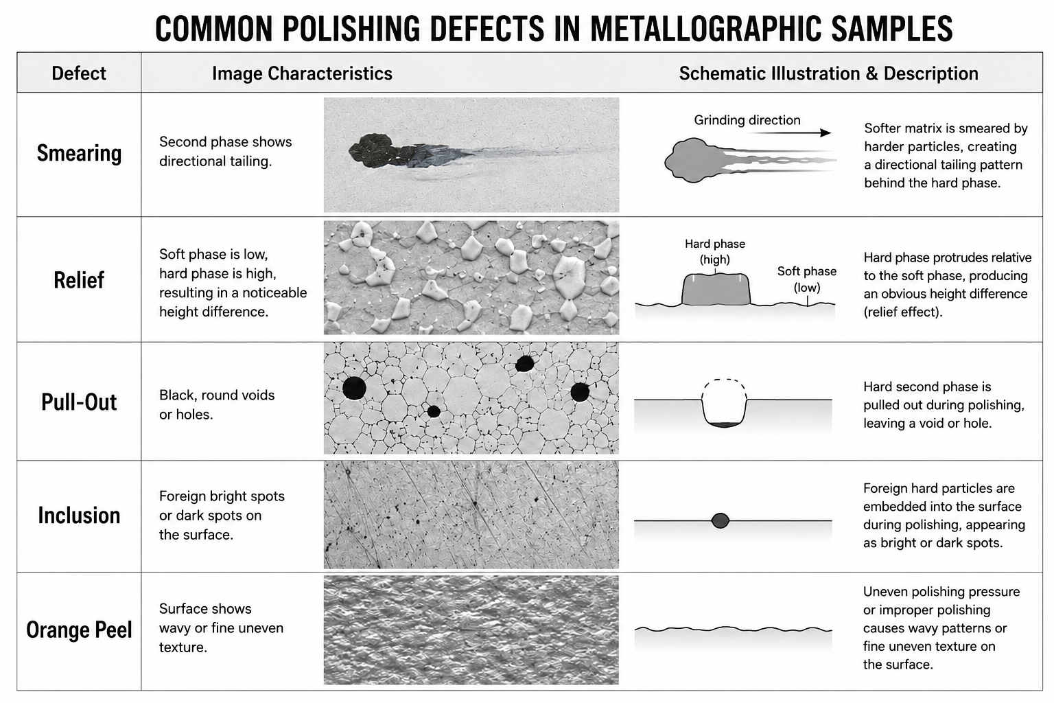
Polishing-related problems are particularly common in composite materials, alloys with significant hardness differences between phases, cast irons, aluminum alloys, copper alloys, stainless steels, thermal spray coatings, and powder metallurgy materials. If the polishing cloth, abrasive particle size, lubricant, applied pressure, rotational speed, or polishing time is not properly matched to the material, defects such as smearing, relief, pull-out, or abrasive embedding may occur.
Common polishing defects and their causes are summarized below:
| Defect | Image Characteristics | Common Cause |
|---|---|---|
| Smearing | Directional tails extending behind secondary phases | Excessive pressure, overly soft polishing cloth, or insufficient lubrication |
| Relief | Soft phases appear recessed while hard phases protrude, creating noticeable height differences | Excessive polishing time or large hardness differences between phases |
| Pull-out | Black pore-like voids | Inclusions, graphite, or brittle phases detached during polishing |
| Abrasive Embedding | Bright or dark foreign particles embedded in the surface | Inadequate cleaning or abrasive contamination |
| Orange Peel | Wavy or uneven surface texture | Excessive deformation of soft metals |
The solution is not simply to polish longer, but to select polishing consumables that match the material's characteristics. Soft materials generally require lower pressure, better lubrication, and gentler final polishing, whereas hard and brittle materials require preparation conditions that minimize pull-out and edge chipping.
Figure 5. Atlas of Common Polishing Defects
3.5 Incomplete Cleaning and Drying: Contamination Magnified Under the Microscope
A specimen surface that appears clean to the naked eye is not necessarily clean under a microscope. Residual abrasive particles, polishing suspension, fingerprints, water stains, alcohol drying marks, or etchant residue can all become significant sources of image artifacts at high magnification. For quantitative image analysis, contamination can further affect thresholding accuracy and phase area fraction measurements.
It is recommended to thoroughly clean the specimen after every grinding and polishing step to prevent abrasive carryover between stages. The specimen should also be dried immediately after cleaning to avoid water stains on the observation surface. For porous materials or castings, ultrasonic cleaning should be carefully controlled to prevent enlargement of fragile phases or edge defects.
3.6 Under-Etching and Over-Etching
Etching is one of the most common causes of final-stage metallographic specimen rework. ASTM E407 provides practical guidance for the microetching of metals and alloys, emphasizing that different materials, examination objectives, and etching conditions all influence the resulting microstructure. Under-etching leaves grain boundaries and phase boundaries insufficiently revealed, while over-etching produces exaggerated grain boundaries, roughened surfaces, and even false porosity, leading to inaccurate interpretation of the true microstructure.
When rework is required after improper etching, the etched surface should first be removed by repolishing before re-etching. Attempting to correct an over-etched surface directly usually results in even greater surface non-uniformity.
Figure 6. Comparison of Different Etching Conditions
| Etching Condition | Microstructural Appearance | Interpretation Risk |
|---|---|---|
| Under-Etched | Faint grain boundaries and indistinct phase boundaries | Difficult to evaluate grain size and phase distribution accurately |
| Properly Etched | Clear grain boundaries with stable contrast | Suitable for reliable observation and quantitative measurement |
| Over-Etched | Dark, widened grain boundaries and rough surface | May lead to false identification of pores, cracks, or secondary phases |
4. Which Preparation Step Should Rework Return To?
The greatest cost of specimen rework often comes from not going back far enough in the preparation process. For example, deep scratches originating from coarse grinding cannot be eliminated simply by extending the final polishing time. Likewise, an over-etched specimen cannot be corrected merely by changing the microscope magnification or adjusting the illumination. Although these approaches may appear to improve the image, they do not remove the root cause of the defect.
| Observed Problem | Recommended Step to Return To | Reason |
|---|---|---|
| Over-etching | Final polishing | The etched surface must be removed before re-etching. |
| Fine scratches | Previous fine polishing or fine grinding step | Final polishing alone may not completely remove directional scratches. |
| Deep scratches | Coarser grinding stage | The scratch depth exceeds the material removal capability of fine polishing. |
| Edge rounding | Mounting and grinding process | Polishing alone cannot restore the original edge geometry. |
| Heat-affected layer | Cutting or specimen resampling | The original microstructure has already been altered during cutting. |
| Severe pull-out | Grinding/polishing parameters and consumables | Mechanical tearing must be minimized and specimen support improved. |
5. Practical Checklist for Reducing Rework
The following checklist is suitable for posting in the metallographic specimen preparation area and can be used for daily operations as well as operator training.
5.1 Before Cutting
- Has the purpose of specimen preparation been clearly defined (grain size, coating, weld, crack, inclusion, or hardness evaluation)?
- Is the sampling orientation clearly identified?
- Is the selected cutting wheel suitable for the material hardness and specimen size?
- Is the coolant supply sufficient, and is the coolant directed at the cutting zone?
- Is the specimen securely clamped to prevent vibration?
5.2 During Grinding and Polishing
- Has every scratch from the previous step been completely removed before proceeding?
- Are the grinding papers or polishing discs free from contamination?
- Are the pressure, rotational speed, and processing time recorded?
- Has excessive grit-size skipping been avoided?
- Is the polishing cloth appropriate for the material being prepared?
- Has the specimen been thoroughly cleaned between every preparation step?
5.3 Before and After Etching
- Is the etchant fresh and properly labeled?
- Has the etching time been verified using a short preliminary trial?
- Has the specimen been rinsed and dried immediately after etching?
- Are unetched or pre-etch images retained for comparison?
- Does the etched microstructure meet the objective of the current analysis?
6. Conclusion: High-Quality Metallographic Images Are the Result of a Stable Preparation Process
Metallographic specimen rework is not merely an operational issue—it reflects the stability of the entire specimen preparation process. Thermal damage introduced during cutting, insufficient edge support during mounting, residual grinding scratches, mismatched polishing conditions, contamination during cleaning, and improper etching can all cause microscopic images to deviate from the material's true microstructure.
Therefore, the key to reducing rework is not simply asking operators to be more careful, but establishing preparation procedures that are standardized, traceable, and repeatable. When the cutting, mounting, grinding, polishing, and etching parameters for every specimen are properly documented and standardized, rework shifts from repeated corrective action to a controllable process improvement activity.
For materials laboratories, a lower rework rate means more than just saving time—it also indicates greater confidence in image quality, improved consistency of microstructural interpretation, and analytical results that provide stronger support for quality-related decision-making.
References
- ASTM International, ASTM E3 – Standard Guide for Preparation of Metallographic Specimens
- ASTM International, ASTM E407 – Standard Practice for Microetching Metals and Alloys
- ISO 643:2019, Steels — Micrographic Determination of the Apparent Grain Size
- ASM Handbook, Volume 9: Metallography and Microstructures
- Vander Voort, G. F., Metallography: Principles and Practice
Editor
Kuo Cheng-Ping
Manufacturing Department, Taiwan Nakazawa Co., Ltd.
Related Press Release
-
 2026 08-19Exhibition
Automation Taipei 2026
Date: 19 – 22 AUG. 2026
Venue: Taipei Nangang Exhibition Center, Hall 1
Booth NO.: J204 -
 2026 07-17Knowledge
How to Reduce Heat Damage in Metallographic Cutting?
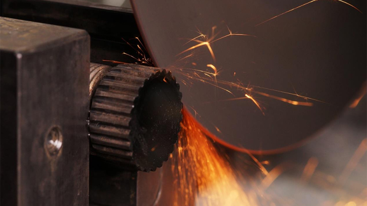
Sectioning is the first critical step in metallographic specimen preparation. The purpose of sectioning is not merely to reduce a material to an observable size, but to obtain a representative cross-section without altering its original microstructure. When excessive heat is generated during sectioning, the specimen surface may undergo tempering, rehardening, phase transformation, oxidation discoloration, plastic deformation, microcracking, or the development of residual stresses. These thermal effects and mechanical damage may persist through subsequent grinding and polishing processes, ultimately leading to misinterpretation of the material's original microstructure during microscopic examination.
-
 2026 05-13Knowledge
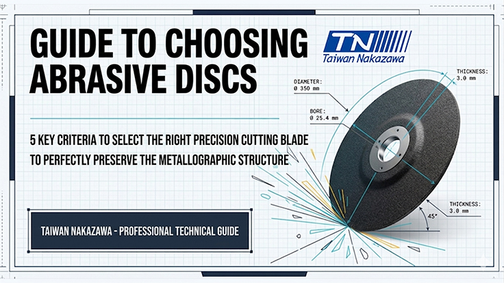
How to Choose the Right Grinding Wheel?
Cutting: The Key to Successful Metallographic Analysis...
-
 2025 10-21Exhibition
2025 TiTE x IHT
Date: October 21–23, 2025
Venue: Taichung International Convention and Exhibition Center (Shuinan) -
 2025 08-20Exhibition
Automation Taipei 2025
Date: 20 – 23 AUG. 2025
Venue: Taipei Nangang Exhibition Center, Hall 1
Booth NO.: J1026 -
 2025 06-11Knowledge
Inverted vs. Upright Metallurgical Microscopes: How Do They Differ from Regular Microscopes?
In the process of modern metal material analysis and quality inspection, metallurgical microscopes play an extremely critical role. The quality of metallographic sample preparation and microscopic observation directly affects the reliability of testing data, which in turn influences a company's judgment on product quality and process optimization.